|
|
|
 |
|
|
|

MS1040
|
|
|
|
|
|
 |
|
|
|
|
|
|
|
|
The MS1040 is the Area Efficient Adaptive FIR Filter IP core with real-time-operation for ASIC hardware.
Our FIR filter is the world's smallest gate count, shortest delay, and most efficient power consumption.
This FIR filter is designed by Mathematec's original technology, SPINOR.
If necessary, we will adjust this IP core to meet the specification of our customer's product in a brief period of time. |
|
|
|
|
|
|
|
|
|
– High-speed FIR filter with real-time-operation
– The tap number, the bit number and the bit precision are customizable through our services.
– The values of coefficients are dynamically interchangeable.
– The world's smallest gate count, and also the world's smallest area size after the layout.
– This FIR filter is best suited for mobile devices, high-speed image processing units, high-speed
communication units, audio processing units, etc.
– Deliverables
>> Synthesizable Verilog RTL source code (Logic Synthesis is confirmed as shown in Figure 3)
>> Comprehensive Verification test bench and its vectors |
|
|
|
|
|
|
|
|
|
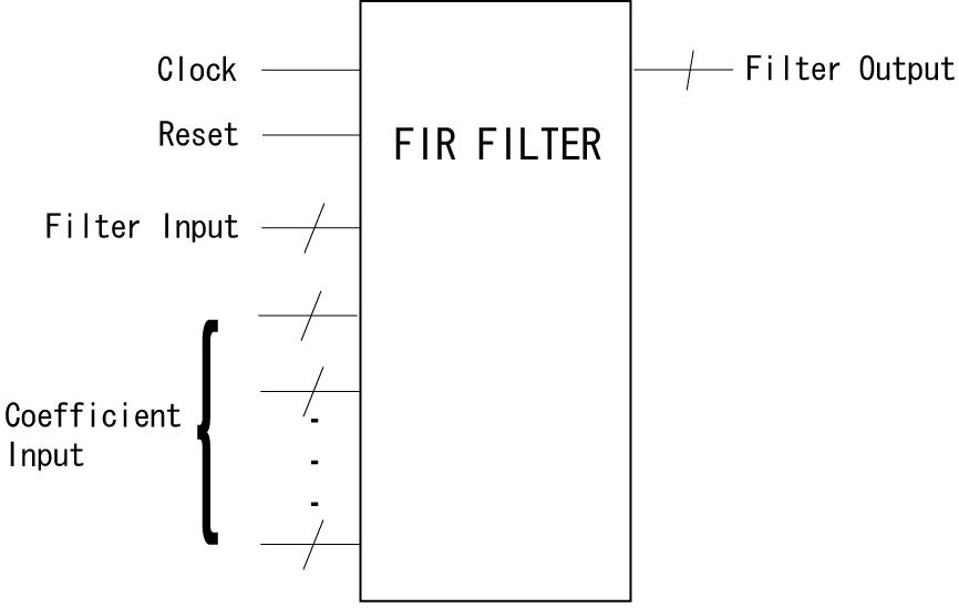 Figure 1 Block Diagram
|
|
|
|
|
|
|
|
|
|
– All of Filter Input, Coefficient Input and Filter Output data are integers in a 2's complement expression.
– The Filter Input data should be entered one by one per clock.
– All of Coefficient Input data should be continuously entered during the filtering processing.
– The Reset is an asynchronous operation. All of Filter Input data in the circuit are initialized as 0
by the Reset.
– Filter Output data are not normalized.
A Filter Output Y is described as the following formula for the case of the number of taps = N,
Filter Input = X[0], X[1], ・・・X[N-1], and Coefficient Input = K[0], K[1], ・・・, K[N-1].
Y=X[N-1]×K[0]+X[N-2]×K[1]+・・・+X[1]×K[N-2]+X[0]×K[N-1]
– Each output becomes valid 3 clocks after its input X[N] is entered. Detail is shown as below.
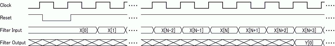
Figure 2 Timing Chart |
|
|
|
|
|
|
|
|
|
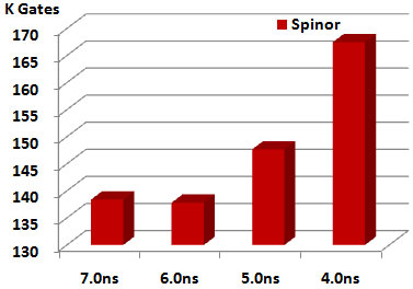
Figure 3 shows the gate counts with conditions of 128 taps, 16-bit width, and real-time-operation as an example. The size of this IP core is depended on a Delay Constraint shown as Figure 3, and our customer can choose any one of them.
The gate count reduction ratio comparing with a common design (see Note) gets larger as the
number of taps increases.
Tools
Synopsys's Design Compiler
Version A-2007.12-SP2
Library ARTISAN TSMC 90nm Gen.
Logic Synthesis Constraints
1. Delay Constraints See Figure 3
2. Maximum Fanout Constraints non
3. Zero Wireload
4. Operating Condition Slow
|
|
Figure 3 Area size & Delay
|
|
Note) Gate count: 2-input-NAND-equivalent
Common circuit: RTL circuit which described with Verilog Operators using the FIR filter's
sum-of-products operations
|
|
|
|
|
|
|
|
 |
|
|
|
|